
Wildcard Week
This week's assignment is to design and produce something using a digital fabrication process, incorporating computer-aided design and manufacturing, not covered in another assignment.
I've decided to create air tight part using a Wire EDM machine.
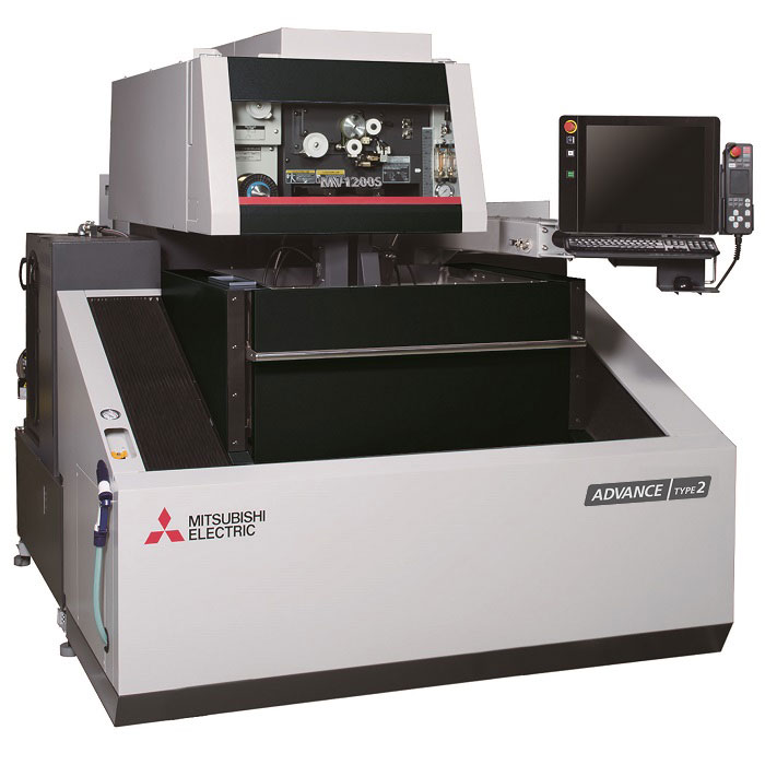
Mitsubishi wire EDM
Wire EDM Machine:
A wire EDM machine utilizes electrical discharge machining principles to precisely cut through materials using a thin, electrically conductive wire. The process involves generating a controlled electrical spark discharge between the wire electrode and the workpiece, which erodes the material to create the desired shape. The wire is typically made of brass or similar conductive material and is guided along a programmed path to accurately cut the workpiece.
Specifications:
- Cutting Capacity: Wire EDM machines can cut through materials with thicknesses ranging from a fraction of a millimeter to several inches.
- Accuracy: These machines offer high precision, with tolerances as tight as a few micrometers (µm).
- Speed: While not as fast as some traditional machining processes like milling, wire EDM can achieve intricate cuts efficiently.
- Surface Finish: Wire EDM produces fine surface finishes, often eliminating the need for additional finishing processes.
- Wire Types: Different types and diameters of wire can be used depending on the material and desired cut quality.
- Control Systems: Advanced control systems enable complex geometries to be machined with ease.
Advantages:
- Precision: Wire EDM machines can produce highly accurate and intricate shapes with tight tolerances.
- No Contact: Since the wire doesn't physically touch the workpiece, there is minimal mechanical stress, reducing the risk of deformation.
- Versatility: Suitable for a wide range of electrically conductive materials, including hardened steels, exotic alloys, and conductive ceramics.
- Complex Shapes: Ideal for cutting complex contours, sharp corners, and fine details that may be challenging with conventional machining methods.
- Minimal Material Waste: The erosion process is very efficient, resulting in minimal material wastage.
- Heat-Affected Zone: Unlike traditional machining methods, wire EDM produces no heat-affected zone, preserving material properties.
Disadvantages:
- Slow Cutting Speed: Compared to some traditional machining methods, wire EDM can be relatively slow, especially for thicker materials.
- Initial Setup Time: Programming and setting up wire EDM machines for specific jobs can be time-consuming.
- Cost: Wire EDM machines and operation costs can be higher compared to conventional machining methods.
- Limited Material Thickness: While capable of cutting thick materials, the process becomes slower and less efficient with increased thickness.
- Wire Breakage: Breakage of the thin wire electrode can occur during machining, requiring interruptions for replacement.
Applications:
- Tool and Die Making: Wire EDM is widely used in the manufacturing of molds, dies, and punches for industries such as automotive, aerospace, and injection molding.
- Prototyping: Its ability to accurately replicate complex designs makes wire EDM suitable for prototyping and small-scale production runs.
- Medical Device Manufacturing: Used for producing intricate components for medical devices such as surgical instruments and implants.
- Electronics: Wire EDM is employed in the production of precision components for electronic devices, including connectors and contactors.
- Aerospace: Critical components like turbine blades and engine parts benefit from the precision and versatility of wire EDM machining.
In conclusion, wire EDM machines offer precise, versatile, and efficient machining capabilities, making them indispensable in various industries where complex shapes and high precision are required despite some limitations and initial setup requirements.
Wire Electrical Discharge Machining (EDM) is capable of cutting a wide range of electrically conductive materials. Some common materials that can be cut using wire EDM include:
- Steel: Including tool steels, stainless steels, and hardened steels.
- Aluminum: Often used in aerospace, automotive, and electronics industries.
- Copper: Widely used in electrical applications and heat exchangers.
- Brass: A popular choice for decorative and functional applications due to its corrosion resistance.
- Titanium: Commonly used in aerospace, medical, and automotive industries for its high strength-to-weight ratio.
- Exotic Alloys: Including nickel-based superalloys used in aerospace and high-temperature applications.
- Conductive Ceramics: Such as tungsten carbide and silicon carbide used in cutting tools and wear-resistant components.
- Precious Metals: Like gold, silver, and platinum, used in jewelry and electronics manufacturing.
These materials are suitable for wire EDM due to their ability to conduct electricity, which is essential for the electrical discharge machining process to occur effectively. Additionally, the hardness and other material properties may influence the cutting speed and efficiency of the wire EDM process.
Designing
For the design, my idea is to create an air-tight "M" measuring 30x30mm.
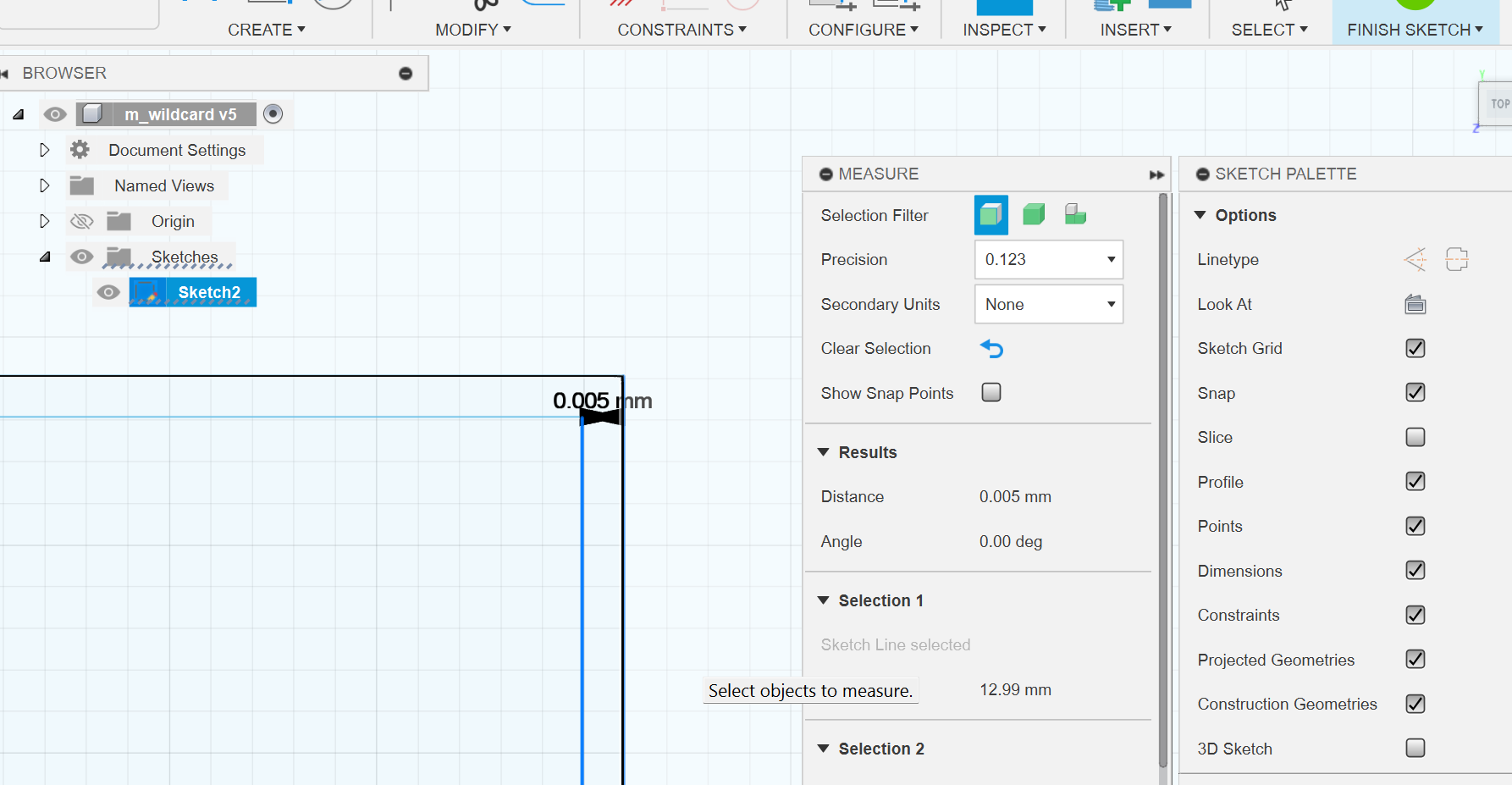
Here is the design for the air-tight "M"
I've applied a tolerance of 0.005mm to ensure it's air-tight.
Here are the rendered images of the design.


Setting up the machine
- Mitsubishi MV1200-s Advance-
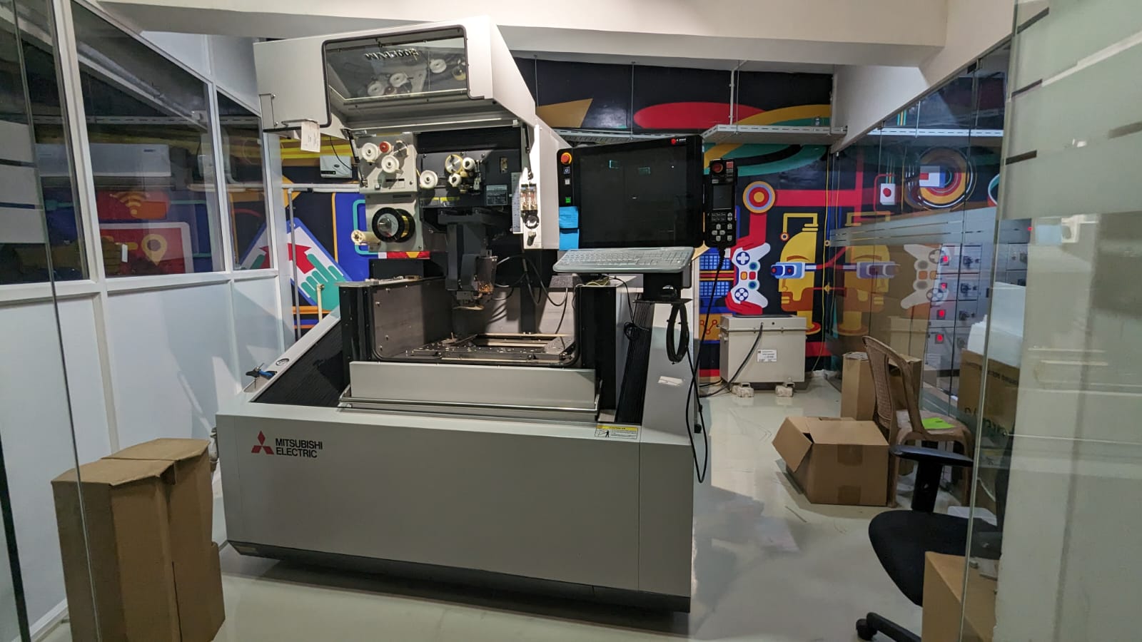
These are the specs of the machine in our lab
| Machine Travels: X x Y x Z in (mm) | 15.7 x 11.8 x 8.7 (400 x 300 x 220) |
| Maximum Workpiece Dimensions: W x D x H in (mm) | 31.9 x 27.6 x 8.5 (810 x 700 x 215) |
| Max. Submerged Workpiece Weight: lb (kg) | 1102 (500) |
| U/V Travels (from center): in (mm) | ±2.4 x ±2.4 (±60 x ±60) |
| Taper Angle @ Thickness: in (mm) | 15 deg.@ 8.0 (15 deg.@ 200) |
| Wide Angle Taper (Optional Guides Required) | 45 deg. @ 1.8″ 45mm (No AT Possible) |
| Table Rapid Feed Speed: in/min (mm/min) | 51.2 (1300) |
| Power Supply | V350-V |
| Minimum Drive Unit / Resolution | 0.000002 / 2 µin ( 0.00005 / 50nm) |
| Wire Diameter Possible: in (mm) | 0.004~0.012 (0.1~0.3) |
| Minimum Start Hole Diameter: in (mm) | 0.02 (0.5) |
| Max. Wire Spool size On Machine / Cabinet STD: lb (kg) | 22 / 44 (10 / 20) |
| Filters / Type | 2 / Paper |
| Filter Tank Capacity: gal (L) | 145 (550) |
| Machine System Dimensions: in (mm) | 79.7 x 106.4 (2025 x 2702) |
| Machine Installed Height: in (mm) | 79.3 (2015) |
| Machine System Weight: lb (kg) | 5952 (2700) |
| Fluid System Weight: lb (kg) | Included with machine |
| Power Requirements [KVA] | 200-230V [13.5] Built in AVR |
| Compressed Air Requirements | 2.7 cu.ft./min. @ 71~100 psi |
Hand Held controller:
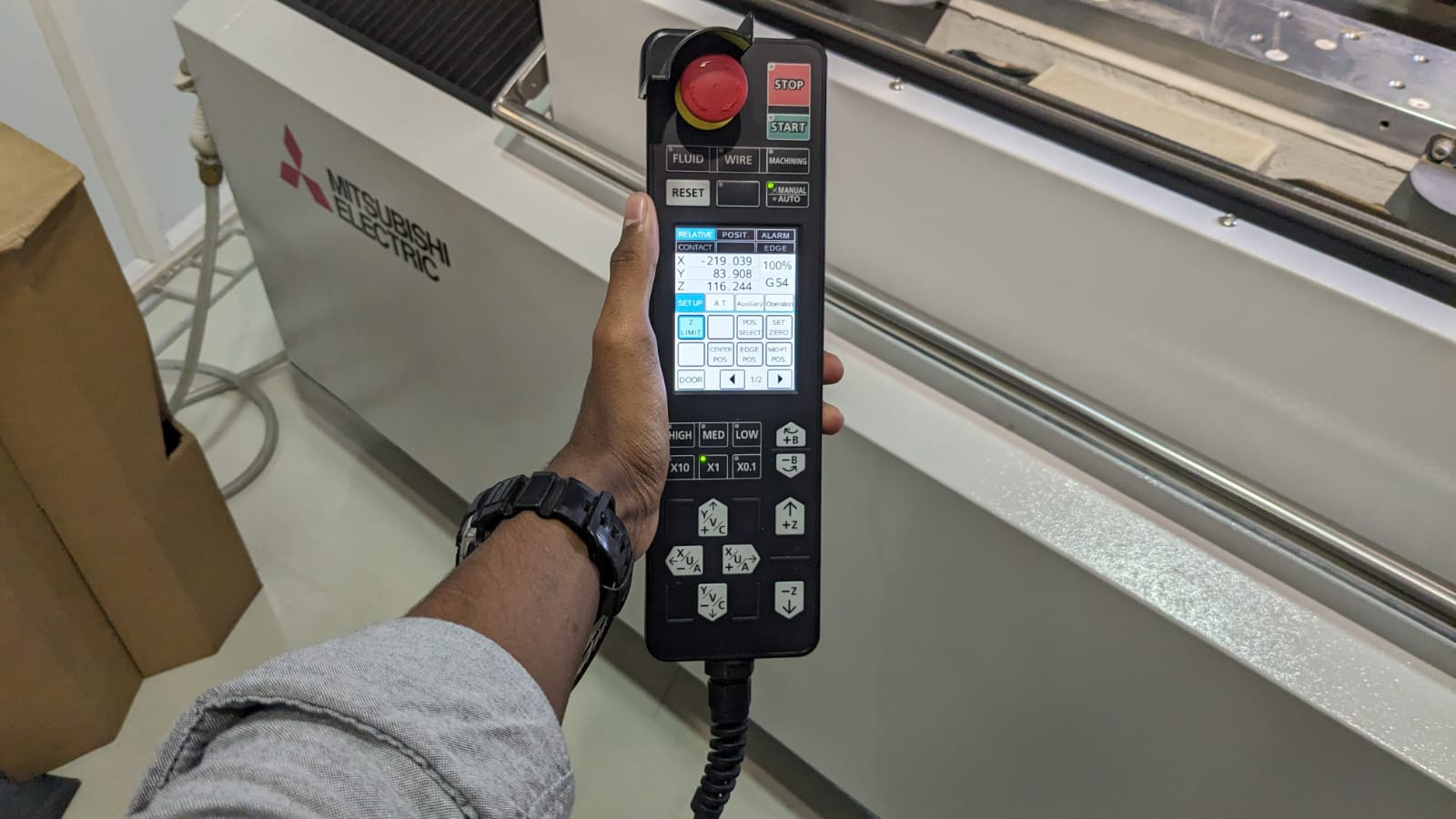
This controller features jog keys as well as functions for operating the “AT” system and more.
AT Mechanism
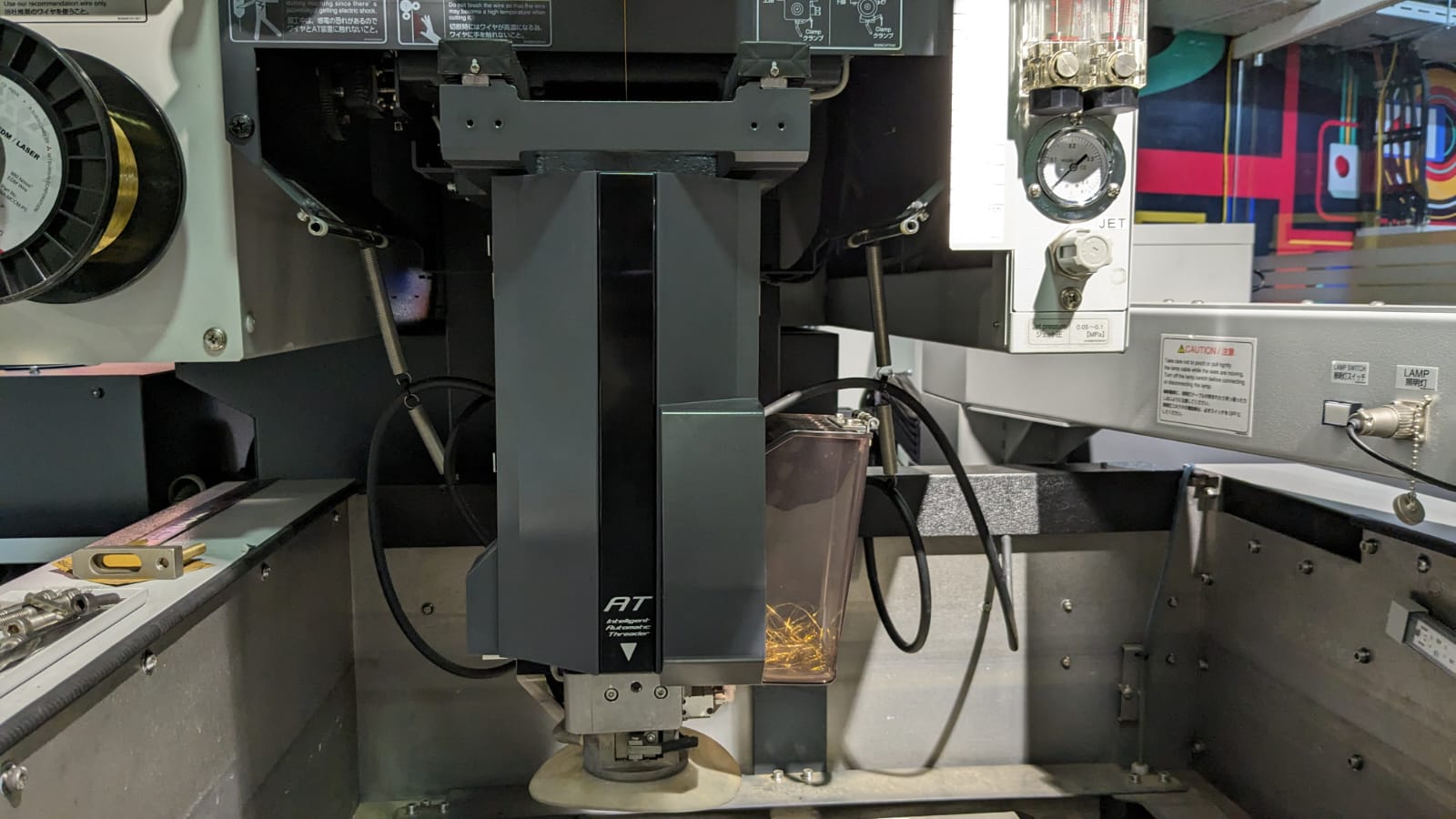
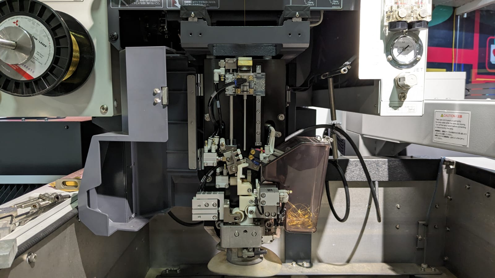
When you open the flap, you can see the actual mechanism, which is a bit complex.
The control of the AT mechanism is available on the handheld controller.
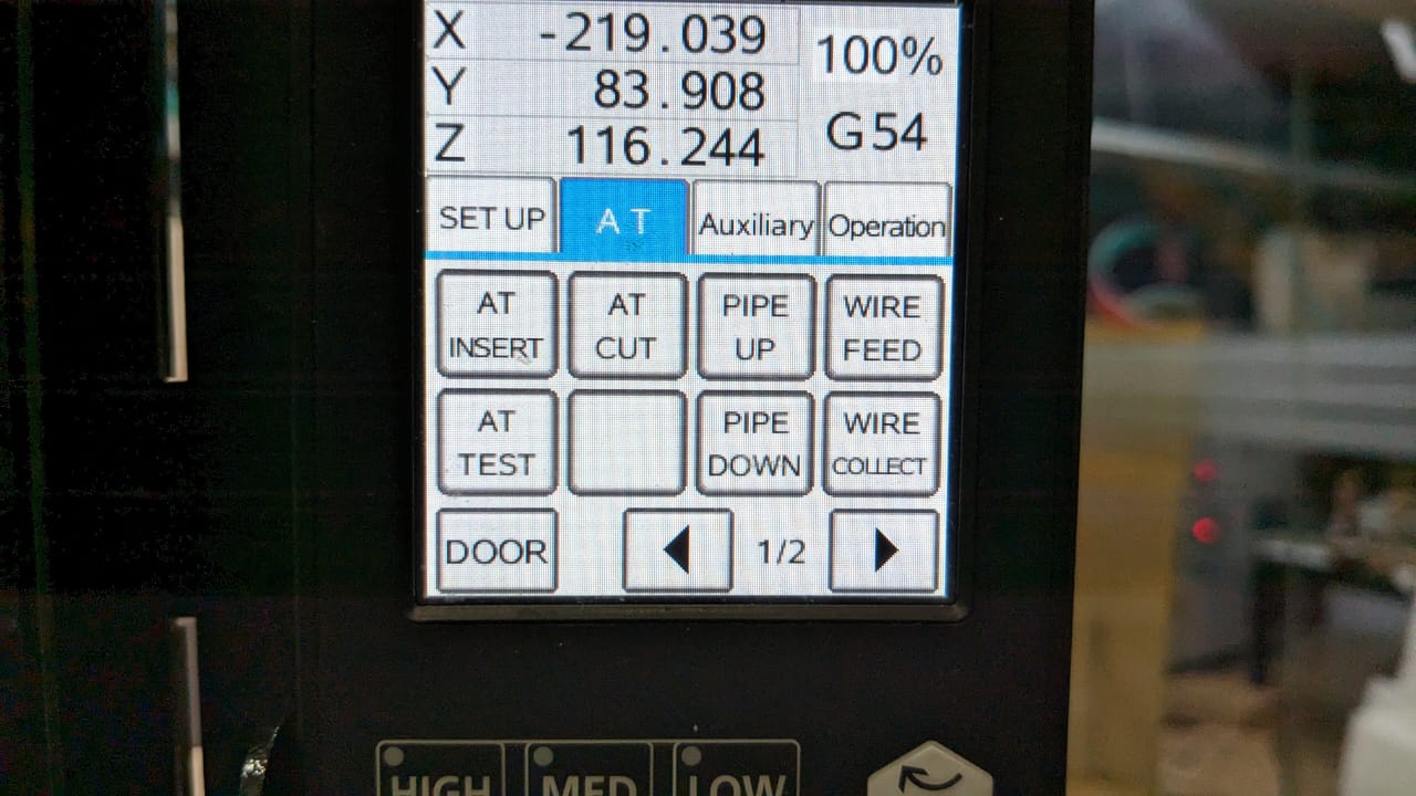
AT Insert - inserts the wire
AT Cut - Cuts the wire
AT test - injects the water through the nozzle
" Pipe up " and " pipe down " are used when manually inserting the wire during failures in AT inserts.
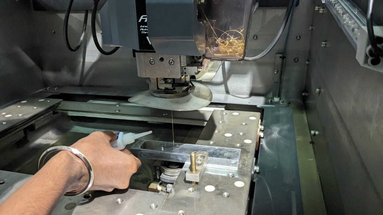
CAM / MACHINE SETUP
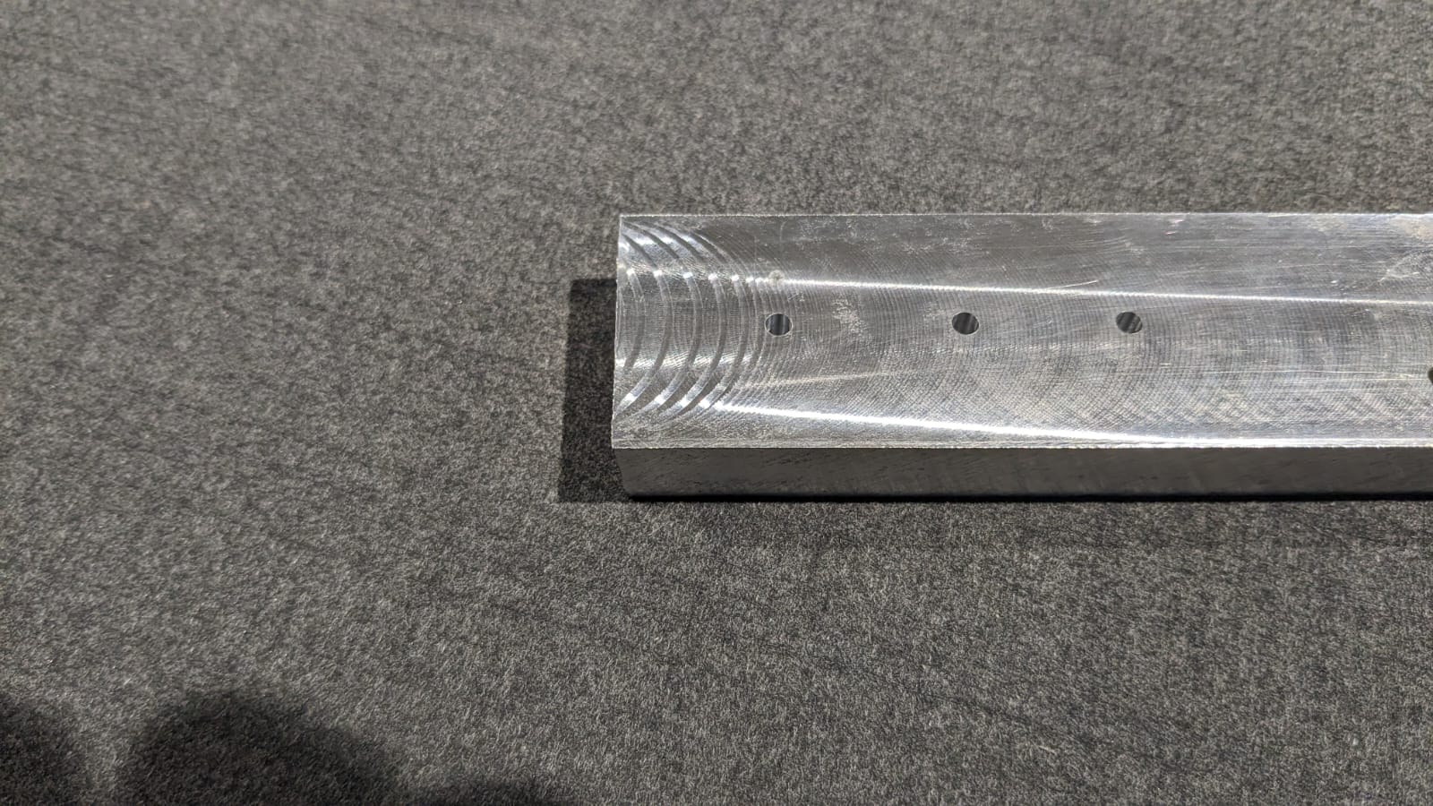
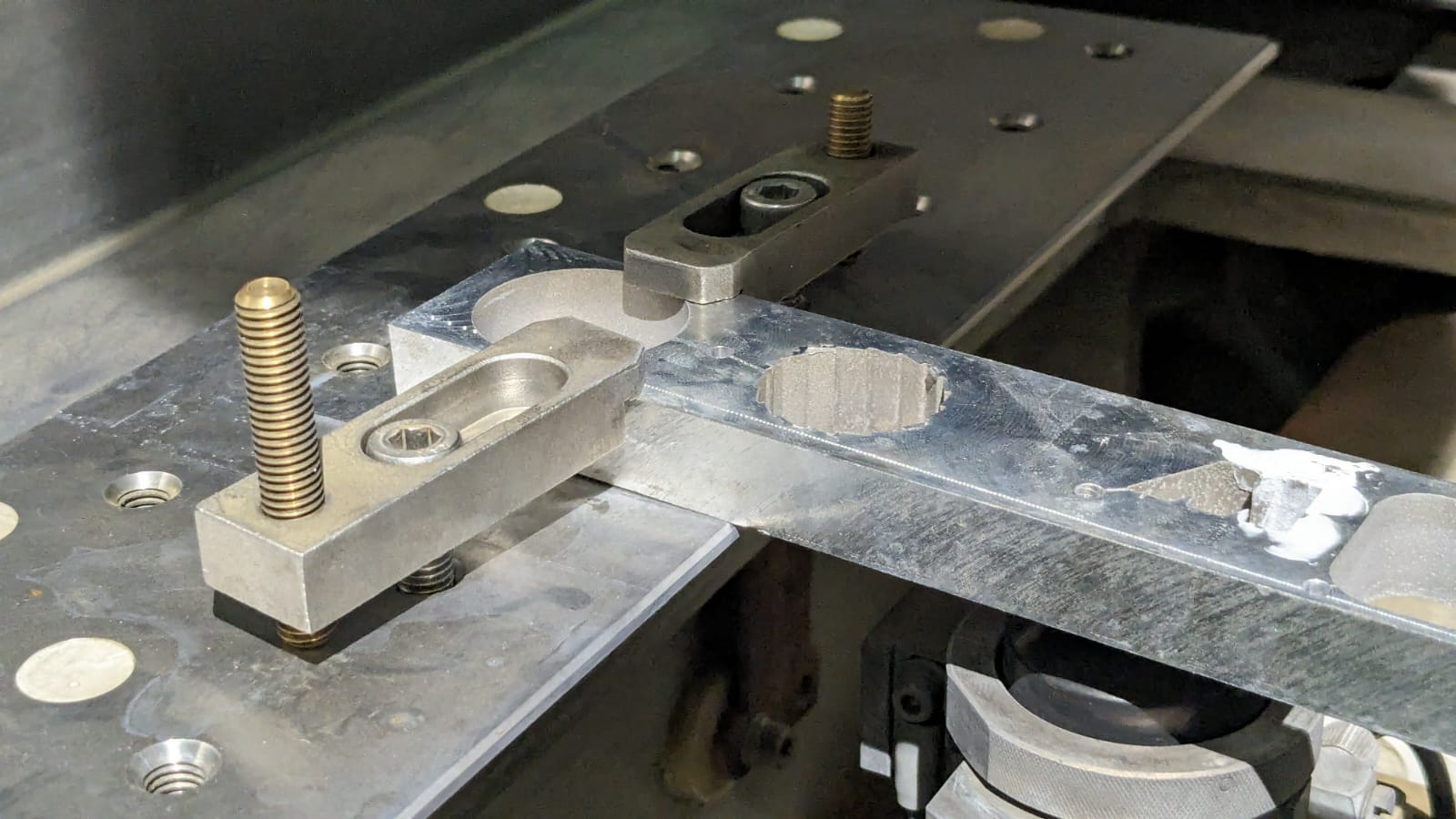
The first step is to find a workpiece and set it on the bed.
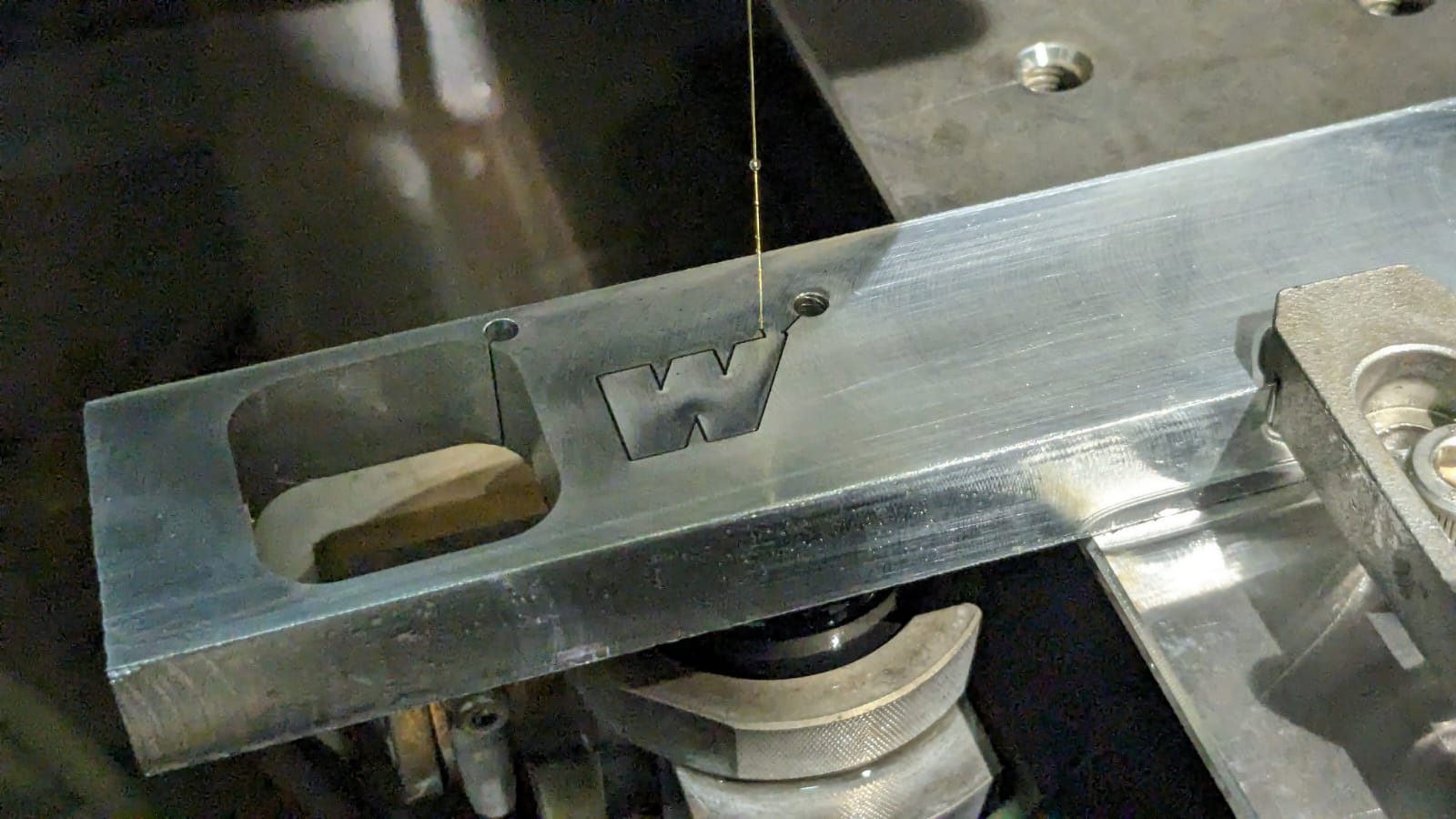
I chose aluminum as the material, with a thickness of approximately 16.3mm.
I manually drilled the required holes for inserting the wire.
Then, I fixed the workpiece onto the bed using clamps.
Once the workpiece is fixed, the next step is to set up the CAM (Computer-Aided Manufacturing) in the machine itself.
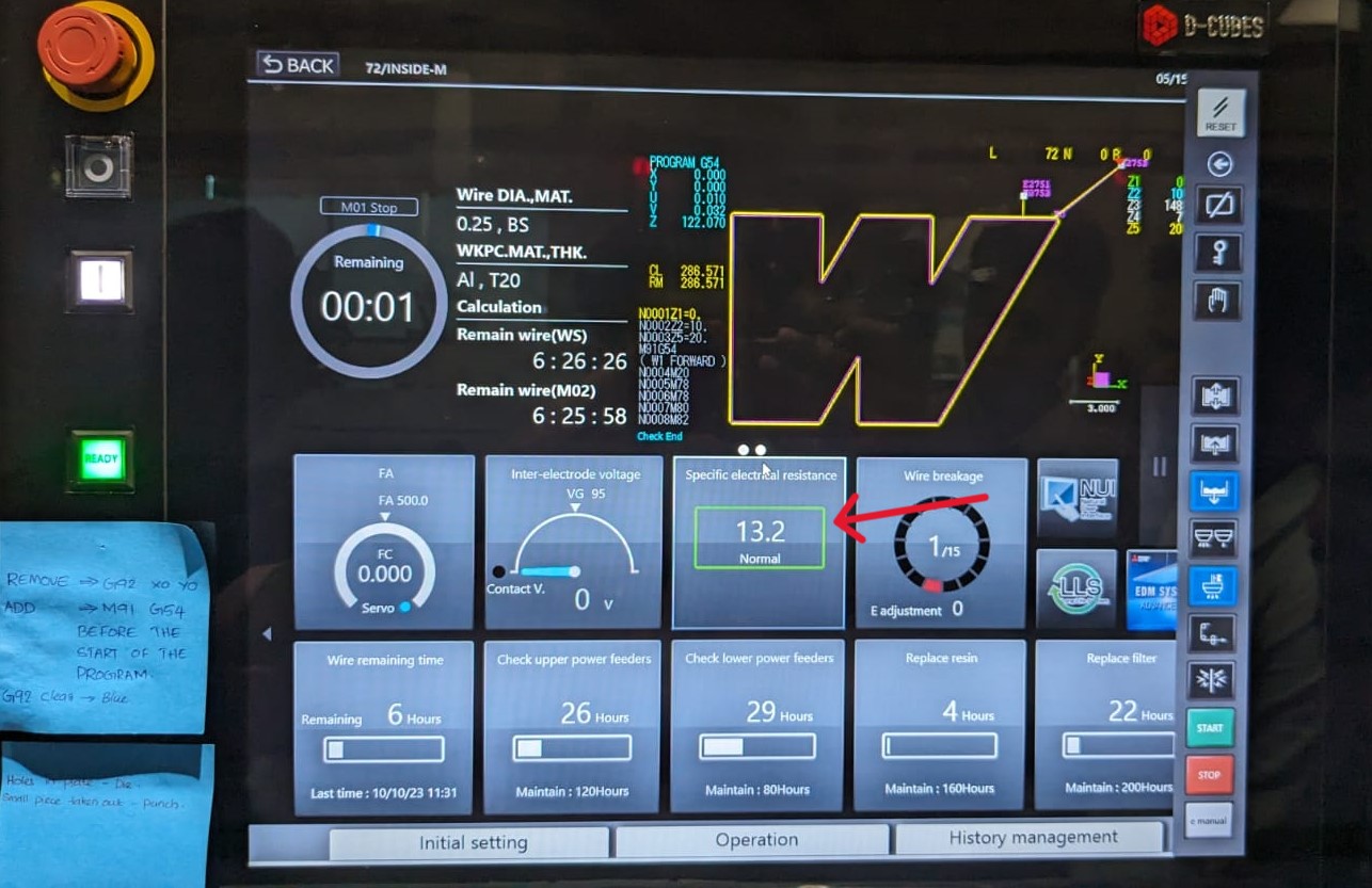
This is the initial screen displayed when the machine starts up.
When starting up, ensure that the " specific electric resistance " is normal. If it's high, add some more dielectric.
Finding the slope
To find the slope, navigate to the operation page and locate the option for work slope . Provide the appropriate distance according to our workpiece; in this case, I've set it to 50mm. The distance refers to the distance between the points where the slope is calculated.
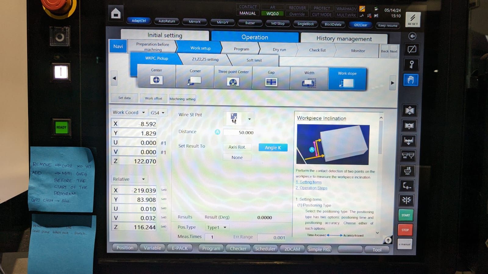
After setting up for the work slope, press " start " on the controller or the screen to proceed.
This will verify the slope of the workpiece and adjust the program accordingly.
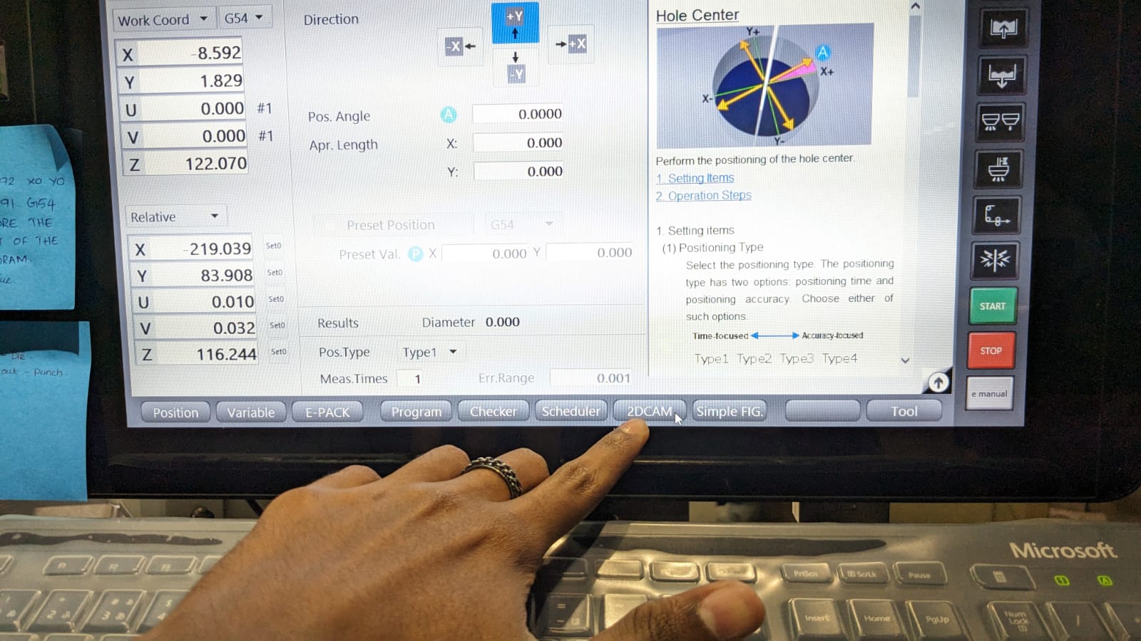
Setting the Origin
To find the center of the hole, I'm selecting the center option. There are various options available for setting the origin, and you can choose one according to the requirement.
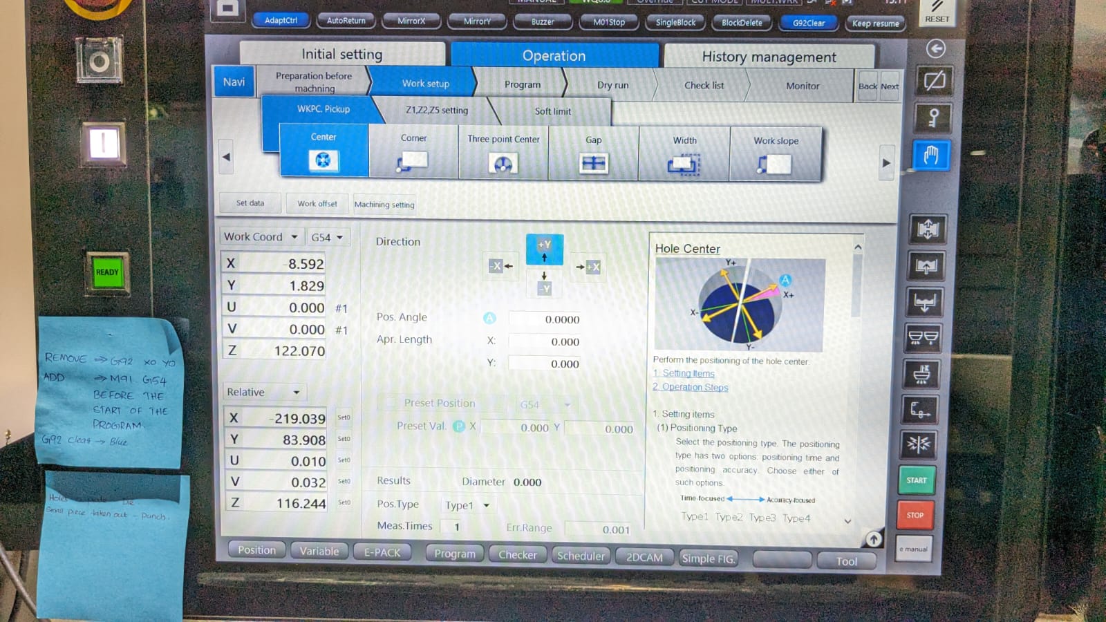
In the center option, I'm setting the position angle as 20 degrees and proceeding with the start button.
After completing the procedure, reset the work coordinates for both X and Y to zero .
Now that the coordinates are set, we can proceed to the 2D CAM . You can find the 2D CAM option on the bottom bar.
In the 2D CAM option, you can open up your .dxf design, and this window will appear.
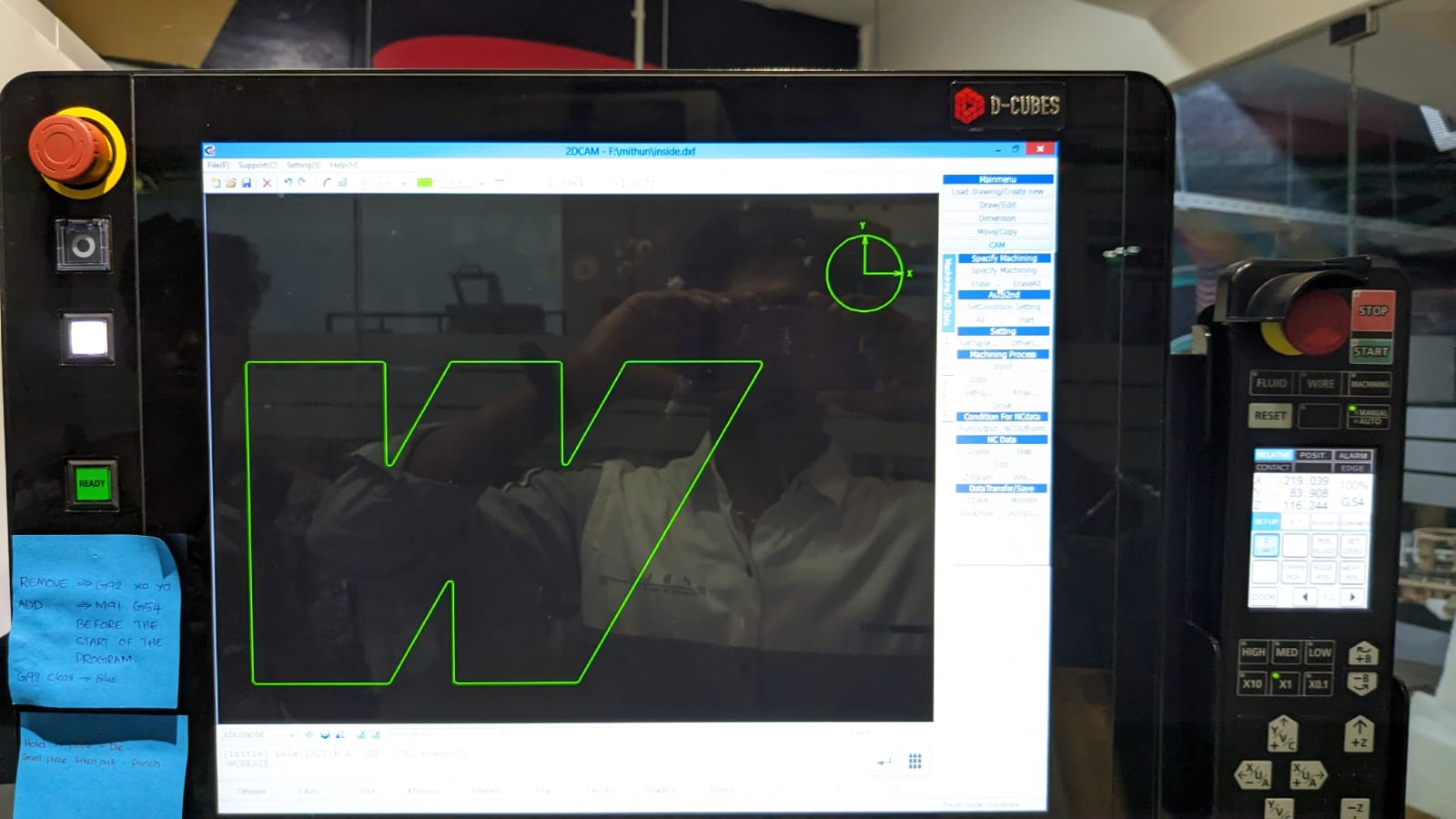
On the left side, there are options.
- Initially, specify the machining by holding the shift key and clicking the circle, then click on the part where you want to start the cut
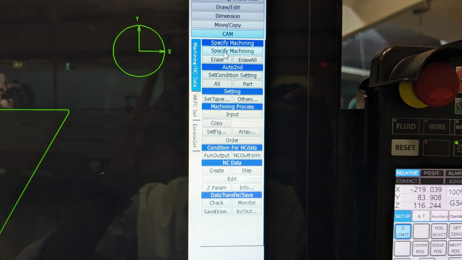
Now that the machining is specified, we need to set conditions for it by accessing the " Set Condition " settings.
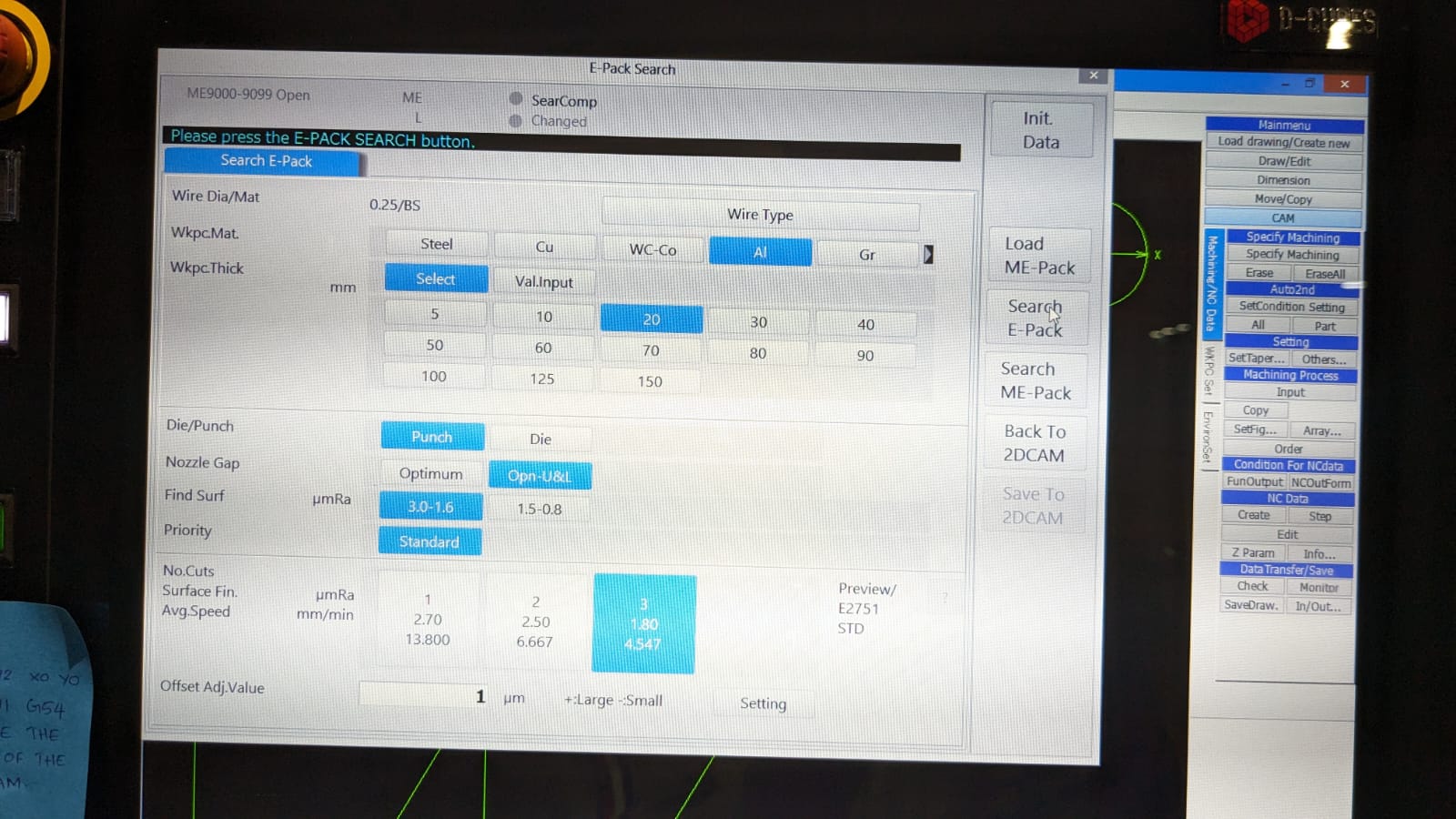
Provide the appropriate data. In my case, I am using aluminum with a thickness of 16.3mm, set the thickness as 20mm , and select the appropriate settings as required.
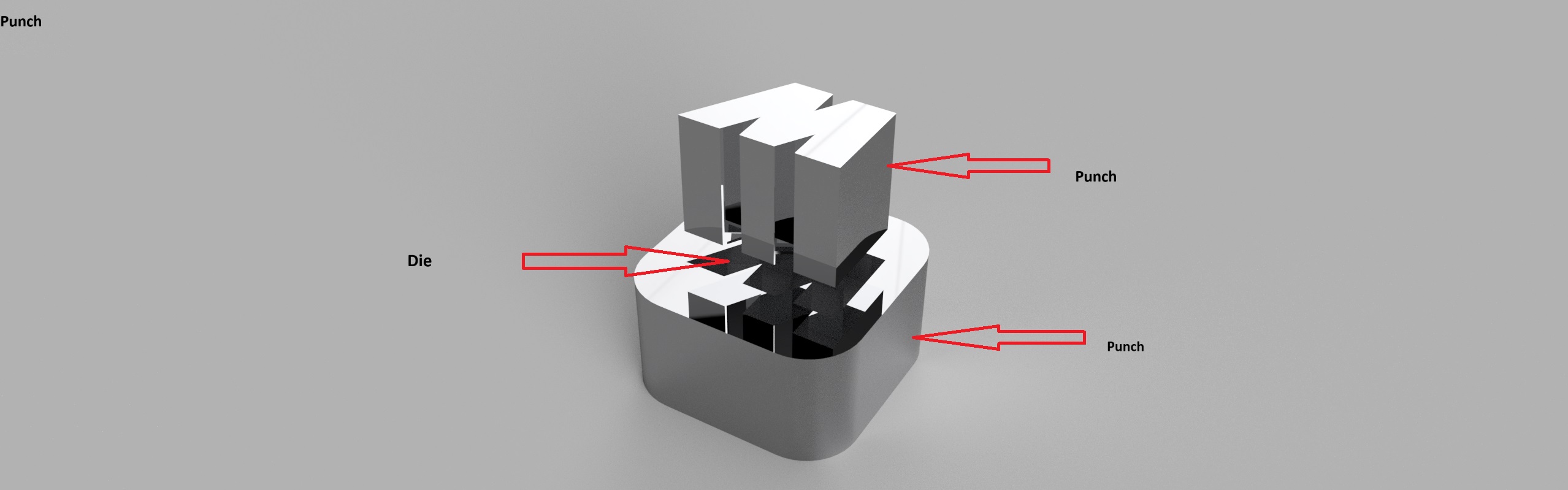
DIE -Hole in plate
PUNCH - small plate taken out
After setting the parameters as per the requirements, click on the " Search E pack " button on the left side.
This will configure the material settings according to the requirements specified. Then, click on the " Save to 2D CAM " button.
This will open another window; provide the options accordingly and click " OK .”
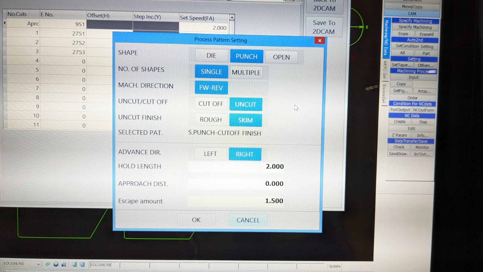
I've set the hold length as 2mm to secure the piece in position until the end of all finishing processes. After all finishing, only that tab will be cut off.
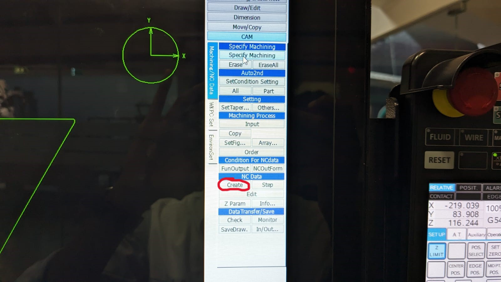
Now, the CAM is ready. Press " Create " to generate the G-code.
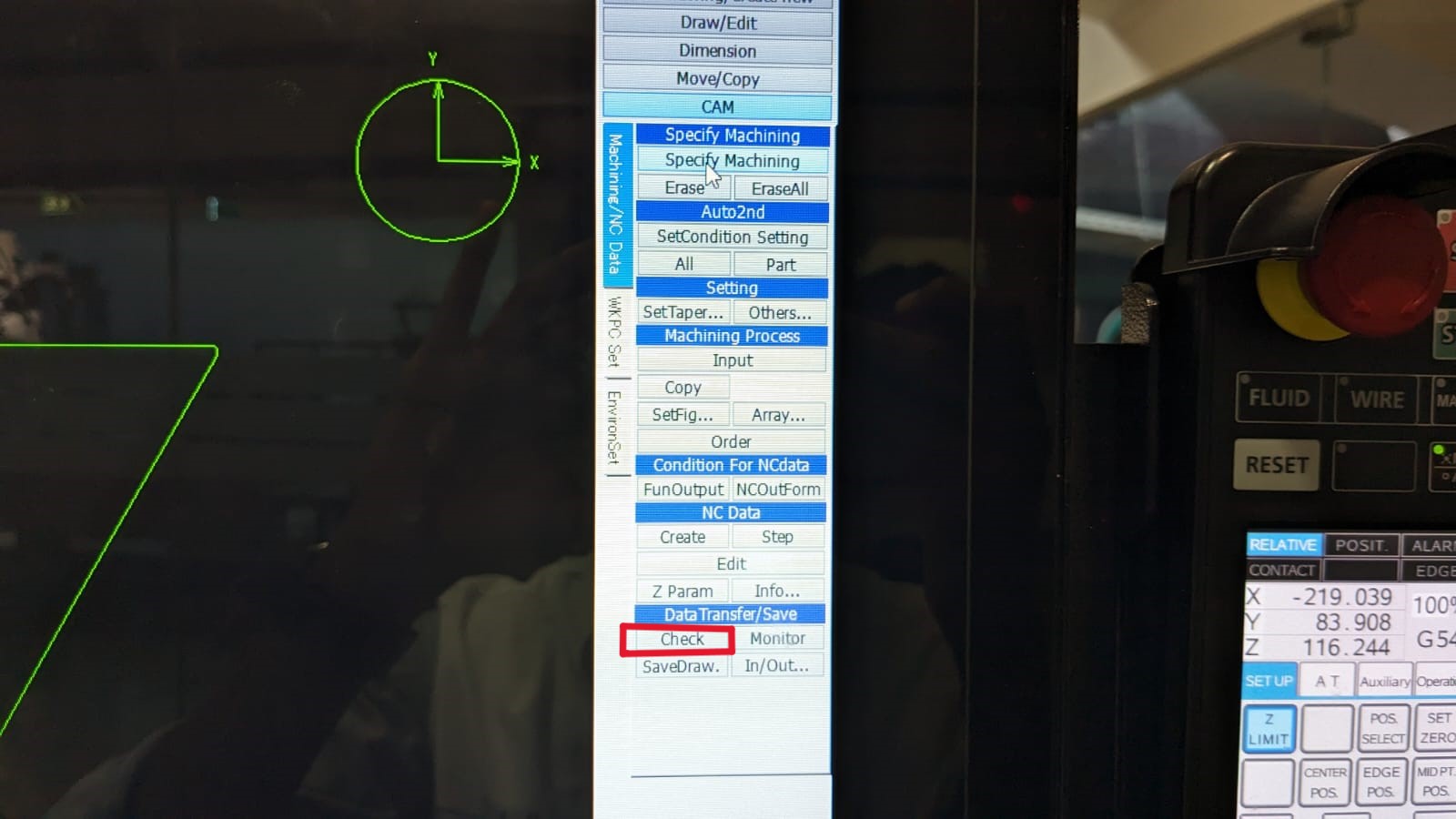
Now, click on the “check” button. This will open a window where you can save the G-code. Save the G-code accordingly.
In the G-code, M91G54 is used to set a predefined point as the origin for the part being machined, in this case, the center of the circle. On the other hand, the code G92X0Y0 is a command in CNC programming that sets a temporary zero point or offset for the X and Y axes at the current position of the tool. Both codes typically serve the same purpose, but we have been advised to choose the former because the latter can only be used in situations where the initial point is set. If the tool is made to travel from one point to another, there is a chance that the operation may fail.
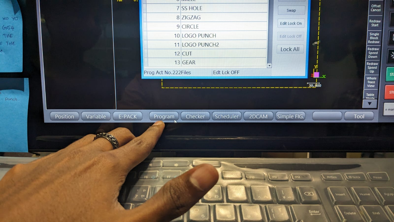
To accomplish this, open the “ program” from the bottom bar. Select the program and click on " Open File ." Add " M91G54 " before the program and then delete the " G92X0Y0 " code from the file.
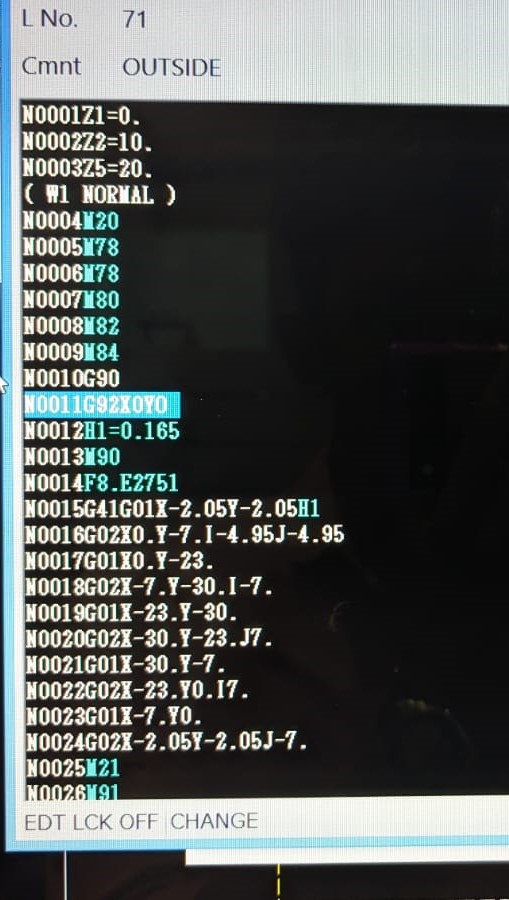
Delete G92X0Y0
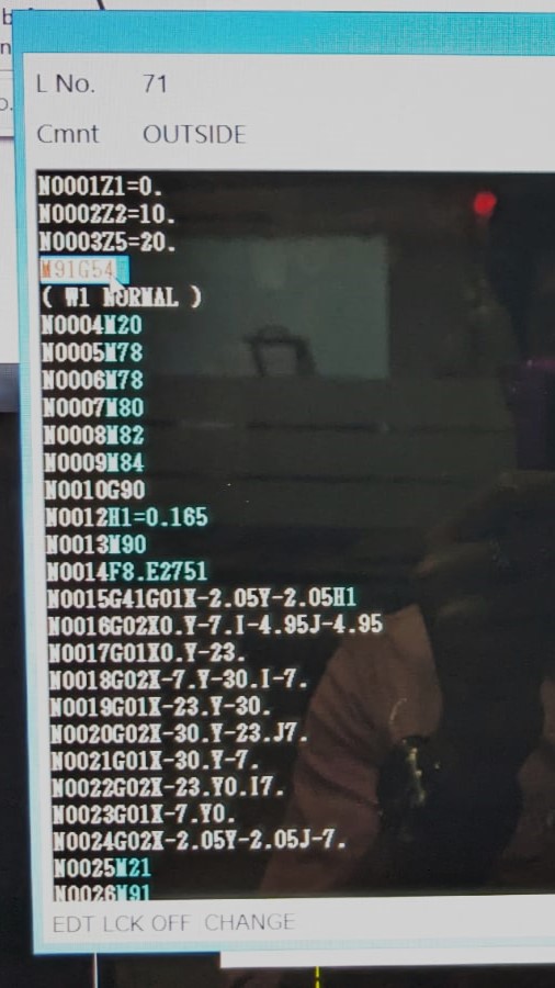
Add M91G54
After editing, save the program and open it to run the program.
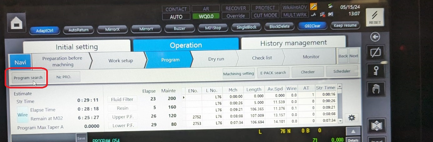
To open the program, click on the " Program Search " option and load the program.
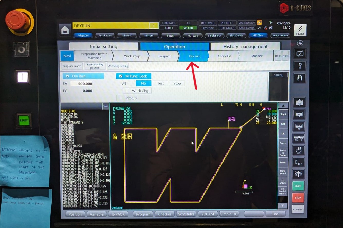
It's always better to try a Dry Run first before proceeding with actual machining. To do this, click on Program > Dry Run and press " Start ". This allows you to see the tool path so you can identify and correct any errors before starting the actual machining process.
If everything seems okay during the Dry Run, we can proceed to start the program. To do this, go to the " Program " section and click " Start " to initiate the process.
Before starting, it's important to keep the nozzle as close to the workpiece as possible and set the Z limit by clicking the Z limit option in the controller. Setting the Z limit is crucial because it allows us to maintain the original nozzle position even if we need to change the Z height while removing the cut pieces or performing any other tasks.
As each operation is completed, the next .dxf file is added, and the process is repeated. In this case, there were a total of 3 operations.
In this case, for the inside of the outer piece where the inner part is not required, I didn't provide any tab. After the first pass, the machine automatically stops so that we can remove the piece manually. It then resumes for the next two passes to finish the operation.
For the inner part, where the cut-off piece is required, I provided tabs. The process involves machining all the other parts except the tab in 3 passes and then stopping. At this point, we have to fix the other sides to the outer part so that it doesn't fall off while cutting the tab.
When the machine stops in between, the first step is to clean the surface. Then, I attach the aluminum chips with the help of Flexkwik to the piece. After that, the work resumes, and the tab is cut in 3 passes.
When I removed the piece, I noticed an issue with the clearance. After a closer examination, I realized the problem was due to leftover Flexkwik. I used a knife to cut away the residue of the Flexkwik.
After completing all the operations, here is the result.
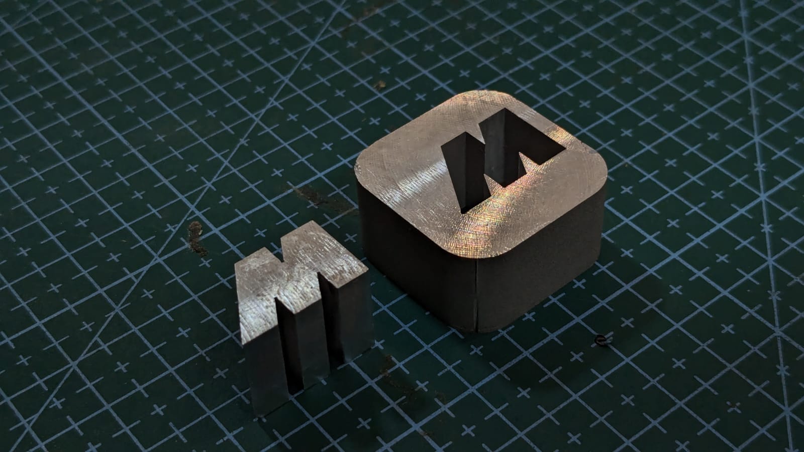
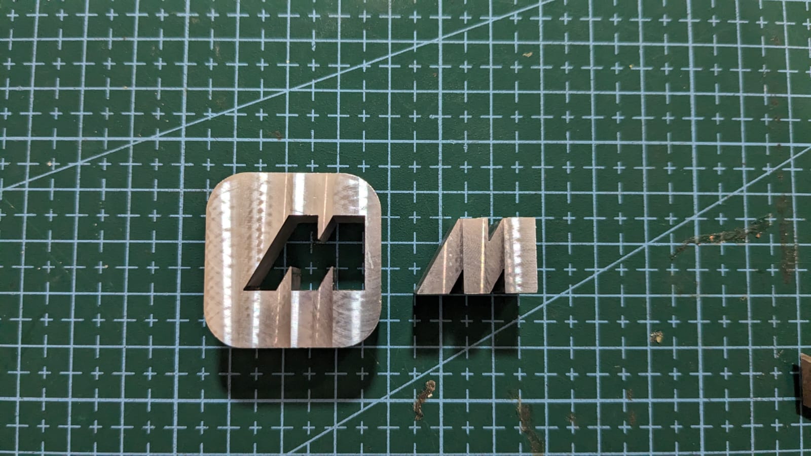
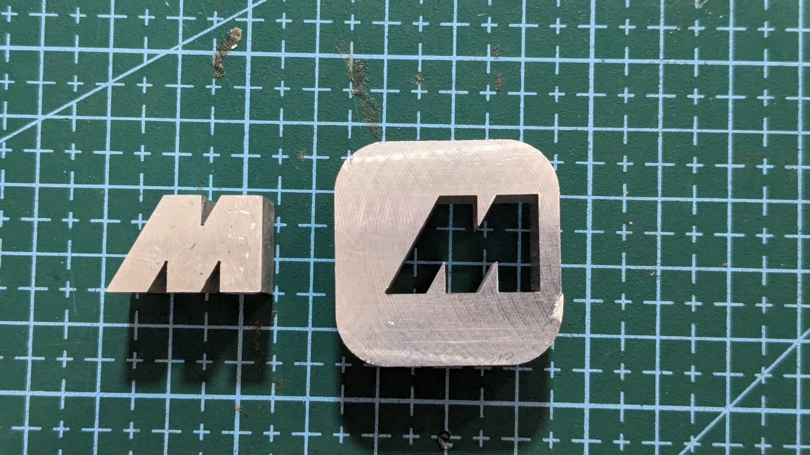
I'm happy with the final outcome; it turned out quite well.